It's always hard to write a blog post after what seems like a hiatus. I have been super busy with my day job and with trying to keep the momentum going on Airball. I have a couple trusted testers testing the stuff, and I will likely de-cloak them (with their permission of course) in a future posting. But for now, let's talk about the tech that has been cooking.
The main feedback from testers is that the display units I've been building are "monsters". There is -- like -- nowhere to put the blasted things. Most people already have their panel full of electronics, and until Airball is at a place where someone can dedicate some of their panel to a real Airball product, things are going to remain that way.
To that end, I have been hard at work developing a display based on a 2.4" sunlight readable LCD:
https://newhavendisplay.com/2-4-inch-sunlight-readable-tft-without-touchscreen/
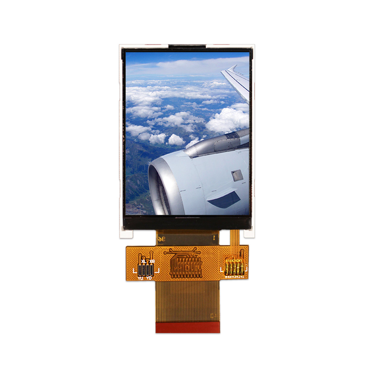
This is a brilliant little unit, with a nice non-glare matte finish. The only thing is, its interface is not something that I can connect to a Raspberry Pi via the "standard" display output. In particular, it uses the Sitronix ST7789VI driver IC, which can use either serial SPI (souperrr slow!) or "8080" style 8- or 16-bit parallel bus input.
Driving the 8080 style bus from a Raspberry Pi requires toggling a lot of GPIOs very quickly. This means that we really need to do some sort of DMA. Hence the challenge: Create a DMA system to write to the bus.
It turns out that getting all the pinouts correct with just point-to-point wiring for everything is well nigh impossible. I made a jury rigged system on a piece of plywood, with intermediate headers for specific signals.

I then started futzing with the software to get all this working. It turns out that the Raspberry Pi has a DMA subsystem -- the Secondary Memory Interface. In forum posts like this and this, I got the help I needed, especially from a poster who goes by "cleverca22" on the RasPi forums. With that and much staring at waveforms on the scope, I finally had things working:

Huzzah! An Airball-like thingey on the screen, at last!
During that time, I also got overwhelmed with my garage and did some cleaning, and also rigged up some self-adhesive LED strip lighting on a cheapy piece of metal angle from Home Depot to act as "under counter lighting".


No comments :
Post a Comment