Saturday, September 30, 2017

PCB for airdata probe

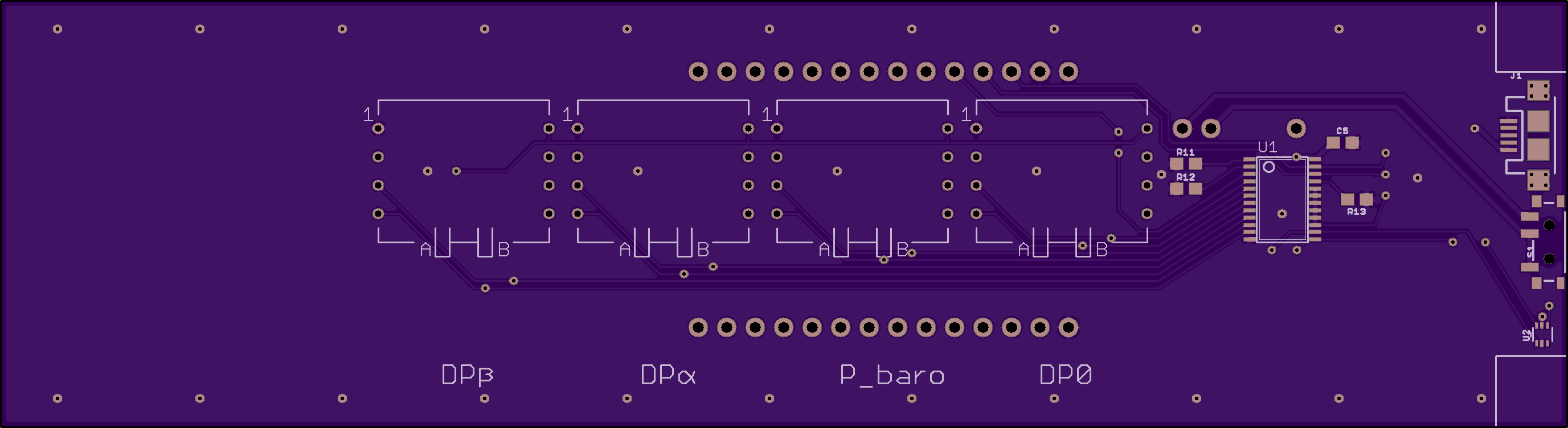
After the humbling experience with the flakey bare-wired sensor board, I decided to spin up a PCB that would bring together all the parts I need. This design has only one "loose" wire pair: the wires to the battery, which is designed to be VHB taped and Zip-tied to the board with the loose wires taped up for vibration protection.

The board at Osh Park is here:


Front:


Back:


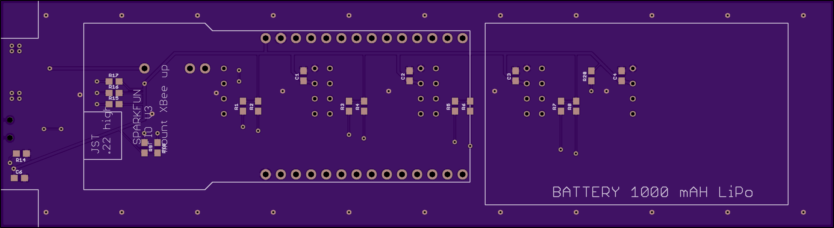
Now I need to CAD up some 3D printed components to fix the board in the polycarbonate tube, and expose the rear board edge since that contains the charging connector, the on/off switch, and a tiny little temperature sensor chip (TI TMP102).

The temperature sensor probably should be in the actual airstream, rather than merely exposed on the board edge, but for the time being this should be a reasonable enough configuration for preliminary testing.

Saturday, September 23, 2017

More dreaded electronic crickets

Today, we tried for a test flight with the airdata probe mounted onto the strut of a friend's Cessna 172. Unfortunately, after getting out to the airport, mounting everything, and sitting in the plane, the probe did not seem to be sending any data to the display. We tried bringing the probe within a few inches of the display, to rule out RF interference problems, and turned both parts off and on again, but no dice.

Part of the problem may be that, in anticipation of the test flight, I repacked the contents of the probe to ensure that they did not jostle around during flight. This may well have messed up the circuits in some way and caused this problem.

Tomorrow we debug.

Saturday, September 16, 2017

The dreaded electronic crickets

My greatest dread and fear is of electronic crickets. I put a circuit together, as carefully as I can, plug it in, and ... crickets. Nothing. Nada. Not a peep. Well so it happened today.

I soldered one I2C mux chip and some resistors and capacitors into the board I had made. Soldering the SMTs was not easy, and it's clear that I need at least a good magnifier of some sort and a good pair of very precise tweezers. I then pulled off some signals from the board to see if the I2C mux would successfully mux in a BMP280 pressure sensor breakout board, thus verifying that at least some of the things I put on there were doing their job.

The result was, no detectable I2C presence.

Ok so I imagine the problem is that I failed to tie the address pins (A1, A2, A3) of the I2C mux either high or low, so who knows what address the thing happens to be sitting on right now. This is a pretty elementary boo-boo, and I note (ex post facto as it turns out) that the Adafruit breakout board does indeed tie these pins low, and provides a way for you to override that.

Another boo-boo I made is that, in the mounting for the BMP280 board, I failed to pay attention to the hole diameter -- I ended up making holes suitable for an IC, but not for a (much thicker) 0.1" header.

So I think I have decided to skip bare board manufacturing for now. I'm sure I can learn the necessary skills but that is for another day.

That said, I can still get boards made to mount the breakout boards into -- that will save me from a lot of flimsy and error-prone hand wiring, and will save some space inside my probe.


Friday, September 15, 2017

Perfect Purple PCBs

I just got my PCBs from Osh Park today. I will be populating these for SMD soldering practice, but I'm going to respin this design before I put any expensive components into it.:

  • The BMP280 breakout board I designed it for ships direct from Asia and, though cheap on eBay, mine has yet to come in. Given small volumes, I'm going to just rely on Adafruit's.
  • I missed some connections to tie various pins explicitly high or low, which for what it's worth might explain the problems I had getting my wire-soldered version to work too....


Saturday, September 9, 2017

More partses!

Today the Cloudbase Engineering mount came in the mail, as did a bunch of SMD components I'm going to try to solder to the PCBs I ordered. The mount looks great and is very nicely packaged with really lovely accessories; looking forward to seeing how it fits. As for the components ... yikes. How am I ever going to solder these resistors and capacitors? We'll see.


Friday, September 8, 2017

New try for a mount

The mount I described here turned out to be a #fail. The wood was not shaped exactly like the strut, so it put "pressure points" on the strut that we worried would deform it. I could have continued carving at the wood, but I decided to try another idea entirely.

I have ordered a mount from Cloudbase Engineering. Marc, the proprietor, is super helpful and offers free shipping and a money back guarantee. The Cessna 172 mount will come with a photography-style lockable ball with a 1/4-20 threaded adapter. I made a bogo-machined ("bogo" because it's embarrassingly heavy, but oh well) adapter that will allow me to keep the ball mount set at the same angle, but remove the probe for charging. It uses a RAM EZY-Mount™ Quick Release Adapter Kit to accomplish the snap-on quick release.

Now I'm anxiously waiting for my Cloudbase mount in the mail....


Monday, September 4, 2017

Weighing my probe

My wooden Cessna strut clamp was too tight on the strut, so I figured I would take another stab at the problem. First I must quantify. So to that end, I weighed the probe, found its CG with attachment hardware, and made a few pictures of how it would look mounted relative to the wing strut:

https://photos.app.goo.gl/sbNs0VVNrMEgh5ut1

I'm going to shop around the various camera strut mount vendors to see if one of them can sell me something that works out of the box. When in doubt, contact the pros? :)

Sunday, September 3, 2017

Ordered my first PCB

Below is a picture of my first-ever PCB that I've tried to get actually made. This holds three All Sensors Corp. pressure sensors, one 6-pin BMP280 breakout board, and one TC9548A 1-to-8 I2C multiplexer. Along with a bunch of pullup resistors and some capacitors on the power inputs. It has one I2C+power input, and one I2C+power output to an off-board temperature sensor breakout board that I would screw to the outside of my probe.


The cost to get 3 of these made at http://oshpark.com/ was just over $20, including free shipping. This work is not on the critical path of any testing at this point. The goals are:
  1. Go through the schematic -> board -> production process.
  2. See what a board looks like in person, and compare it to my design.
  3. Determine how my traces went -- any places where wires are too close?
  4. Show to an experienced friend and get feedback.
  5. Go through it with a multimeter and look for wiring mistakes.
  6. Buy some SMD parts and practice stuffing the board.
  7. With the board partially populated (without soldering in the really expensive All Sensors chips), determine if it actually works.
  8. Get some DIP headers and attach one of the All Sensors pressure sensors, and see if it works.
I'd be pretty surprised if all of these steps went well, but we'll see.

In general, the long-term goal is that I'm trying to develop and "in house" capacity to build PCBs since this will quickly become my limiting factor. I need to be able to miniaturize my work so as to make it (especially the probes) really lightweight, which in turn will make the probe mounting simpler and easier (if it's no heavier than a GoPro, then any little GoPro mount ought to work).

Saturday, September 2, 2017

Sensor board schematics

Working on a sensor board -- this is my first foray into Eagle. The results of today's hacking.