Monday, January 16, 2023

Mockup of next-gen probe

Today, I put together a mockup of the next-gen probe design. This was to determine the ergonomics of how things would go together, and generally get a feel for what the finished result will be like.

First, I installed threaded inserts and brass nipples in the nose, and attached the tubing from a mock PCB with mock pressure sensors. The 1/16" holes in the ball nose were pretty clogged up from the Shapeways production process and needed to be cleaned out with a drill (previously, I could just flush them out with water). This tells me that any future probe noses should be designed with "drill accessible" holes -- i.e., there should be no sections of the holes which cannot be cleaned out by a drill. This also means, as a side benefit, that these designs could be machined.


The next step is to assemble the back. The temperature sensor is sandwiched between two layers, and there is a detail allowing the power cable to be threaded through then clamped. This step would require sealant to be applied to the faying surfaces.


Now the power cable from the outside, and the QWIIC cable from the temperature sensor to the PCB, need to be attached to the PCB. Imagine in the following picture that they are attached.


I then added four 1.25" long #4 socket head cap screws, added rubber spaces to hold the PCB in securely, and clamped up the whole assembly.

Getting the tubes scrunched in there was a total pain. Conversely, if I had made the tubes shorter, it would have been hard to get everything together properly. Along with the labor to create and attach the hose nipples and attach the tubes, I think this proved to me that the tube-less design is really important.

The polycarbonate tube seemed not to fit perfectly, implying I need to work on tolerancing a bit more. It is possible that, with this shorter design, a probe body made completely of 3D printed parts is more feasible.


And now with the parts together, we can think about installation. As per the renderings you may have seen previously on this blog, I used a 1/2" diameter tube with a yoke -- here 3D printed, but to be made of aluminum in a flight article.

The first photo shows it with a flashlight body attached, and the second without. The first case would be for battery powered use -- the flashlight body gives us a "free" secure battery holder and on/off switch. These are sold as flashlight hosts online. In the second case, the wire would snake into the airplane via the wingtip, for example:


This would integrate with our mounts directly. Here I have used some spare mount parts to illustrate the idea. Our mounts have 2 jaws running on 2 1/2" tubes. The probe tube would serve as the top one, and the bottom one would be for stability. The probe tube would have to be a bit longer to allow the mount jaws to open and fit over the wing strut, but you get the general idea:


Overall, I learned a bunch from this. At a high level, I am convinced that a smaller probe of these dimensions is necessary in order to make Airball accessible to more people. And again: Tubeless is the way to go! Stay tuned for more news!

Friday, January 13, 2023

Thoughts about simplified probe build

I have been thinking about ways to further simplify the build of the probes. You may recall that the probes have a lot of hoses inside them to transfer pressure from one place to the other. The hoses, and their fittings, end up being one of the main things that take up room and require hours and hours of labor to fit. You'd think a few hoses would be easy, but these things are tiny, and they need to be super secure or else they pop off while the probes are in use. So I put my mind to seeing if we can eliminate these entirely.

The Honeywell pressure sensors I use look like this:


Note how they have little barbed fittings for hoses. Theoretically, Honeywell makes the same parts with barbless tapered fittings, which look something like this:


These would be really cool to use since they seem perfect to "slot into" some kind of one-piece manifold with no plumbing required -- only a seal of some sort, or a dab of sealant. Wouldn't it be great if I could get these?

Except no. Honeywell does not talk to small timers like me. We are left picking at table scraps from the stock that the electronics suppliers happen to have on hand. Which is primarily the ones with barbed connectors. Sigh.

The design I am tossing around in my mind looks like this:

This is a fitting onto which the pressure sensors, on a small daughterboard, are attached. Basically, the realization is: It is easier to route electrical signals around your design than it is to route pneumatic pressure. So put the pneumatic stuff in a convenient location, and run a wire to your electronics as needed.

In this case, the pressure sensor daughterboard has a tiny JST connector on it carrying the 7 signals I need. Since these are SPI sensors, the signals are 3V3, GND, MISO, SCLK, and 3 chip-select signals.

The fitting would be designed so that the barbed tips of the pressure sensors fit into it, surrounded by a soft sealing tube. In a cross section, it would look like this:


The sealing parts are basically short pieces of tubing, perhaps dabbed with sealant on the outside and then stuck into the holes. The tubing can then be trimmed flush with the surface with a razor blade, and then the daughterboard with the sensors can be mounted.

I tried this out briefly with some scrap plastic and a piece of soft silicone tubing, and it seemed to work out pretty well. If we take this to its logical conclusion, we can have a daughterboard for the barometer (a tiny chip) and the thermometer (also a tiny chip). Both of these are I2C devices, so we need a 4-pin connector:

A key part of this design is the back side of the manifold. It would contain a sort of "anthill" of small grooves going hither and yon to route the pressure:


These would in turn be sealed by layers of gaskets:


The whole assembly would be pulled tight by thru-bolts as with previous designs.

It turns out (nothing in this world is new...) that I have thought these thoughts before, in http://www.airball.aero/2018/02/probe-nose-progress.html. This was in the context of making probes with hoses, though; I was not thinking about using this technique to do away with hoses.

Given the relative ease of snaking wires around and moving SPI signals, it is possible -- extreme, but possible -- to put each of the 3 pressure sensors on its own separate board, and it would still not take up a lot of room, because the 1mm-pitch JST PH connectors I would use are still super small; this is what the 6-pin ones look like.

I'm still bouncing this around so all the ideas above are super preliminary, and the actual CAD work is hacky and contains a bunch of errors. That's fine. I am a very visual thinker, so I usually need to draw something in 3D to appreciate all the details and think of alternatives.

Monday, January 9, 2023

A mini-er mini display

The C++ hacking I described in my last blog post was to clean up the event queue in the code so that I could reasonably add some input devices, namely, an adjustment knob. I now have that working. Let's see how this came together....

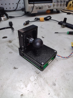
First the interesting part. Here is the new display (which you might note is 1/2" shorter due to the better positioning of the display connector). It is connected to an Adafruit Rotary Trinkey via a generic USB hub. Imagine that the display is mounted on the glareshield of an airplane somewhere, while the rotary knob is accessible on the panel or in some other easily reachable location. Note how I use the knob to adjust the barometer setting, and (finally! woo hoo!) the LCD panel brightness:

The display board, like its predecessor, is very unassuming -- other than having the correct backlight LED driver part (duh!):

The mounting is via a RAM ball on the back, as with the previous one:

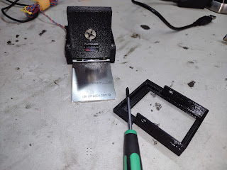
In designing where the flex circuit was to come out, I ended up putting it on the same side as the SD card on the RasPi, meaning that the LCD panel covers the SD card. This required some trickery to make the bezel removable for access to the card. In the end, this was probably not a bad compromise. It leaves the other connectors free for use.

Overall, this is a big step forward and likely my last iteration of this design until we go to a truly custom and truly mini board with a Raspberry Pi Compute Module 4. Stay tuned for that!