Today, I put together a mockup of the next-gen probe design. This was to determine the ergonomics of how things would go together, and generally get a feel for what the finished result will be like.
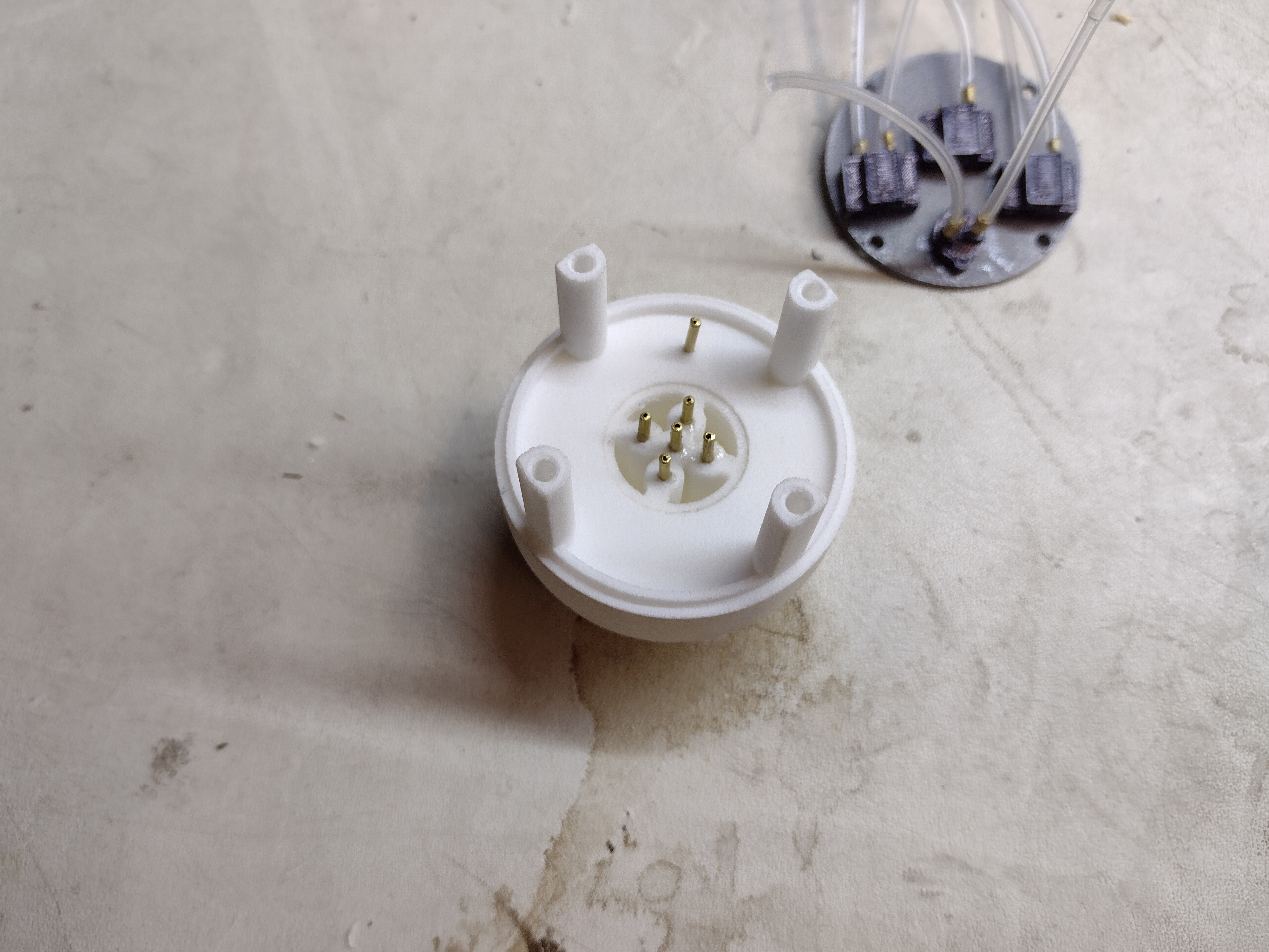
First, I installed threaded inserts and brass nipples in the nose, and attached the tubing from a mock PCB with mock pressure sensors. The 1/16" holes in the ball nose were pretty clogged up from the Shapeways production process and needed to be cleaned out with a drill (previously, I could just flush them out with water). This tells me that any future probe noses should be designed with "drill accessible" holes -- i.e., there should be no sections of the holes which cannot be cleaned out by a drill. This also means, as a side benefit, that these designs could be machined.


The next step is to assemble the back. The temperature sensor is sandwiched between two layers, and there is a detail allowing the power cable to be threaded through then clamped. This step would require sealant to be applied to the faying surfaces.


Now the power cable from the outside, and the QWIIC cable from the temperature sensor to the PCB, need to be attached to the PCB. Imagine in the following picture that they are attached.


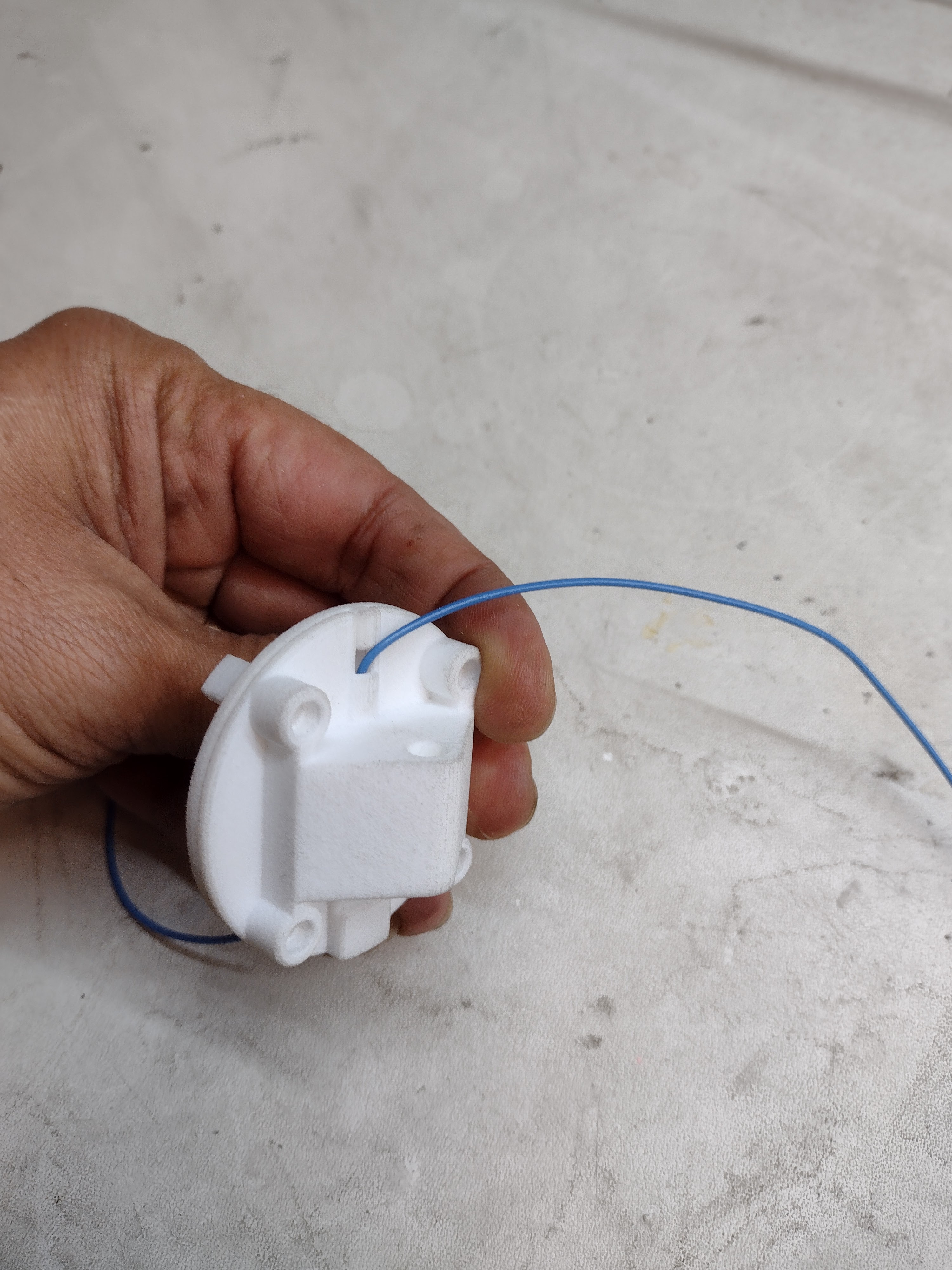
And now with the parts together, we can think about installation. As per the renderings you may have seen previously on this blog, I used a 1/2" diameter tube with a yoke -- here 3D printed, but to be made of aluminum in a flight article.
The first photo shows it with a flashlight body attached, and the second without. The first case would be for battery powered use -- the flashlight body gives us a "free" secure battery holder and on/off switch. These are sold as flashlight hosts online. In the second case, the wire would snake into the airplane via the wingtip, for example:


This would integrate with our mounts directly. Here I have used some spare mount parts to illustrate the idea. Our mounts have 2 jaws running on 2 1/2" tubes. The probe tube would serve as the top one, and the bottom one would be for stability. The probe tube would have to be a bit longer to allow the mount jaws to open and fit over the wing strut, but you get the general idea:


Overall, I learned a bunch from this. At a high level, I am convinced that a smaller probe of these dimensions is necessary in order to make Airball accessible to more people. And again: Tubeless is the way to go! Stay tuned for more news!
No comments :
Post a Comment