Lots has been going on, which I'll try to talk about here. One of the important aspects is the development of a new probe, as you have seen before. The existing design is large and heavy but -- most importantly -- it requires a lot of labor to build! Without further ado, let's talk about what I'm planning.
Electronics
The core of the probe is this very simple "main board" PCB, containing an ESP32-C3 (chosen for its small size) and some power electronics.
I'm using the integrated antenna on the ESP32 to save space; I'll see how that works out, and I can always switch to a model with a U.Fl connector and an external antenna.
Note that I am trying to plan for 12-28V input, and adding CANBus capability. I am not sure how much of that I will use right away, but it can be depopulated if I don't need it yet.
For programming, I added a header to match an Adafruit pogo pin clip to save on parts count and cost. All the USB/serial and "board reset" functions can be on a separate programmer board.


.png)
The first thing this connects to is a small I2C board with a thermometer and a barometer:


The second is a board holding the three SPI pressure sensors, with an 8-pin JST-SH connector for power, the SPI signals, and chip selects:


All this is done using 2-layer PCBs. All but the barometer / thermometer board could probably be hand assembled; the baro and thermometer chips are super tiny and would be frustrating to do at home. In practice, I'm probably going to have PCBWay send me boards populated with everything but the expensive Honeywell pressure sensors, and take it from there.
The cables are easy to get ready-made, which is important because the tiny JST SH connectors are very hard to crimp at home. The I2C cable is intended to be a 50mm QWIIC cable. The cable for the SPI sensor board is a 30mm cable used by FPV enthusiasts.
I am assuming the JST SH connectors are vibration resistant. If this turns out to be wrong, I can re-tool. For example, I could move to positively locked ZIF connectors and FPC cables.
Mechanical
This is all packaged up in the usual combination of 3D printed parts and a polycarbonate tube. This is held together by four #4-40 screws (not shown here). All the 3D printed parts you see are intended to be made by SLS, MJF, or some other "pro" process, not on a Prusa. The parts that support and mount all this can be made on a Prusa. The total cost of one set of the parts you see here, at Shapeways, at Qty=1, is about $50.
This is a series of sections through the stackup showing how the pieces form a series of manifolds.


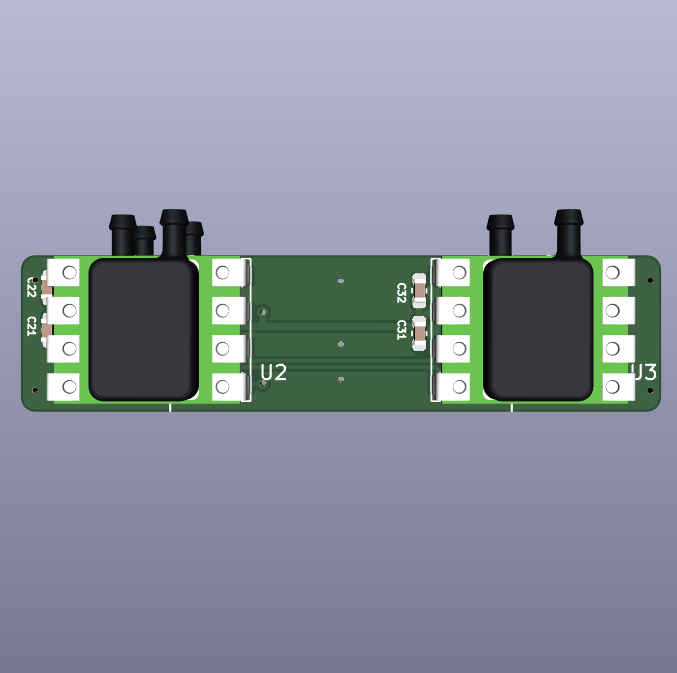
And this is a view from the back showing how the populated side of the main board looks:

No comments :
Post a Comment