Saturday, December 31, 2022

Some C++ hacking

Happy new year (in a few hours...) everyone! :)

Over the past few days, I've been hacking the Raspberry Pi C++ display code to make it more manageable. Previously, it was a pile of spaghetti that grew like a mushroom. Now I have a new repo for the code:

https://github.com/airball-aero/airball-display

In particular, I needed to add support for an adjustment knob, and this required dealing with Linux input events and multi-threading and what not, and if I had not cleaned up the code first, it would have been well nigh unintelligible.

The basic abstraction I added is a class Application which contains an instance of IEventQueue. The event queue acts like any other in a GUI app -- GUI events are posted to it by various threads, and the paint thread processes these events and paints, according to the frame rate. A better or worse human than I would have made the event queue a singleton, but I am worse or better than that, and am for now trying to stick to my "singletons are evil" religion.

This allowed me to add a bunch of code in class Settings so there is very rudimentary support for a (usually USB) adjustment knob -- either a commodity one like this; an Adafruit Rotary Trinkey for more embedded cases; and a custom circuit for even more embedded cases. By using the Linux HID support, I can just plug in via USB and don't have to deal with reading button presses via GPIOs and what-not.

It works, at least on my PC. I'm calling it a night. Here's to a productive and happy 2023!!! <3

Sunday, December 18, 2022

Mounting details for new probe concept

As promised, I did some more CAD work to describe how I imagine the new probe fitting into the scheme of things. Recall the "less is more" mantra. With that in mind, this is how I imagine it will work with the kinds of strut mounting systems we've been building so far:


The thing at the rear is the battery holder part of a flashlight. These are actually sold for $12-$15 as "flashlight hosts" for DIY flashlight makers, for example:

https://www.mtnelectronics.com/index.php?route=product/product&product_id=412

It should be easy to make electrical and mechanical adapters to fit a 18650 version on the end of one of our poles, and run a power wire to the probe. The good thing is, these things come with a water-resistant power switch built in:


That way, we abdicate all responsibility for battery charging -- just replace the battery -- and we also avoid the mechanical hassle of having to create a moisture-resistant battery holder ourselves from scratch.

For a more permanent installation, I imagine mounting as a pole on the wingtip. My friend Paul Eastham (an early Airball supporter) wrote an article for the EAA about these, where a certain you-know-what was featured, using ... um ... "repurposed bicycle inner tubes". Engineering on the cheap is where it's at here. Check out Paul's article here:

Great Airborne Images Within Reach

So given a 3/4" pole of any sort, it is easy to imagine mounting this probe to the end of it, and running a thin power wire in the obvious way -- perhaps into the wingtip of the airplane, and perhaps to sip a little bit of power from the wingtip lights.


It is possible to imagine feeding data via a wired method, so I am hoping to add the ability to send RS-232 signals as well. As for how to step-down an aircraft's power to something that 5V electronics can use, what I've been using is these super-cheap "battery eliminator circuits" from the radio-control world. You can get them at the hobby store, and even Adafruit has caught on!

Stay tuned as I iterate on these designs. Hopefully they can come to fruition in the next few months!


Saturday, December 17, 2022

A new probe, probe-ably

Among the things I'm working on these days is a new probe. The current probe, if you recall, looks like this:

It works pretty well, but it has a number of important disadvantages:

  1. It is large and heavy.
  2. The brass static pressure probe is unwieldy.
  3. The sheer amount of labor required to put it together is immense!
I didn't really anticipate this last factor, but it's important! So -- I am now working on a new one. It will look something like this:


Note how I have preserved the "thru-bolts" assembly, which has worked very well for me in the past, but I have tried to integrate the spacers and other doo-dads as part of the 3D printed pieces, to save time and hassle. Some important attributes of this probe are:

More compact. I am cramming everything into a 2-sided, 4-layer PCB that fits inside the 2" diameter tube.

Less is more. I am eliminating the battery charging circuitry; it will be externally powered either from ship's power or from a flashlight battery holder. So far I don't even have battery voltage monitoring, but I might want to add that. We'll see.

Built-in adjustment. Since it is very light, it can have a series of simple built-in pivots allowing it to be adjusted as needed.

The above is not the entire design -- I have some thoughts about the mountings as well. But this is what I have drawn up so far. I will post more soon.
 
You might notice that the pressure hole scheme is different: There are 2 holes on either side of the "ball nose" instead of the bulky static pressure probe. I have performed a wind tunnel calibration of this configuration and I believe that, with the data I have, I can get good results. I will be sharing separately the story of my recent wind tunnel work. Stay tuned for that.

I have also been designing the PCB for this. In the process, I am moving from AutoDesk Eagle to KiCad, which is really exciting. The PCB work in progress is at:

https://github.com/airball-aero/airball-hardware/tree/main/compact-probe


One of the things I'm hoping to try is to add a 5x2 1.27mm pitch header to the edge of the board (look for J1 in the renderings), and use an Adafruit pogo pin clip for programming. The pogo pin clip would connect to a "programmer" board which would contain all the USB/serial logic and transistor network necessary for programming this thing with the standard Arduino utilities. Hopefully, this makes it easy to program, but also saves precious board real estate.

Thursday, December 15, 2022

New high brightness 2.4" mini display

It's always hard to write a blog post after what seems like a hiatus. I have been super busy with my day job and with trying to keep the momentum going on Airball. I have a couple trusted testers testing the stuff, and I will likely de-cloak them (with their permission of course) in a future posting. But for now, let's talk about the tech that has been cooking.

The main feedback from testers is that the display units I've been building are "monsters". There is -- like -- nowhere to put the blasted things. Most people already have their panel full of electronics, and until Airball is at a place where someone can dedicate some of their panel to a real Airball product, things are going to remain that way.

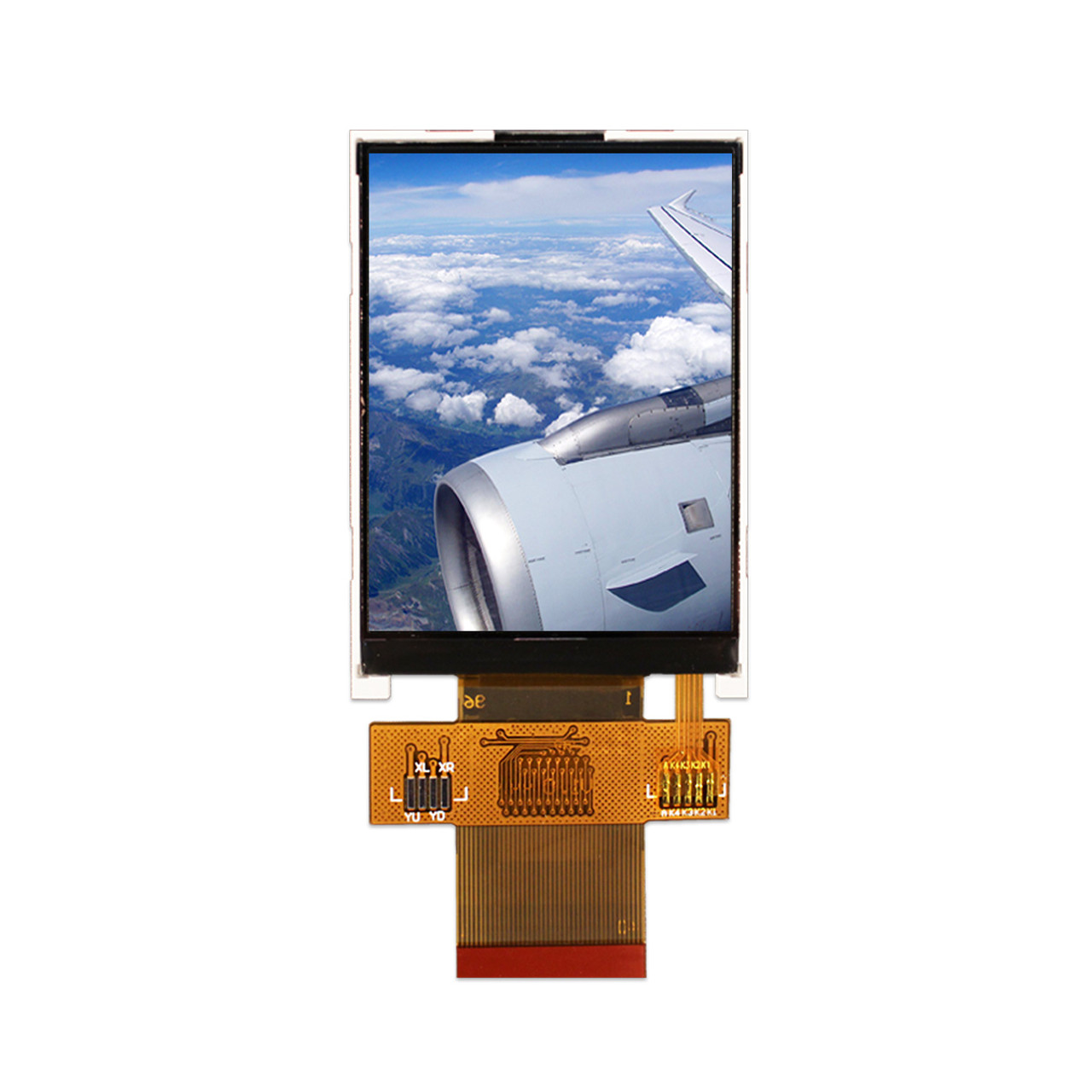
To that end, I have been hard at work developing a display based on a 2.4" sunlight readable LCD:

https://newhavendisplay.com/2-4-inch-sunlight-readable-tft-without-touchscreen/


This is a brilliant little unit, with a nice non-glare matte finish. The only thing is, its interface is not something that I can connect to a Raspberry Pi via the "standard" display output. In particular, it uses the Sitronix ST7789VI driver IC, which can use either serial SPI (souperrr slow!) or "8080" style 8- or 16-bit parallel bus input.

Driving the 8080 style bus from a Raspberry Pi requires toggling a lot of GPIOs very quickly. This means that we really need to do some sort of DMA. Hence the challenge: Create a DMA system to write to the bus.

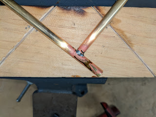
It turns out that getting all the pinouts correct with just point-to-point wiring for everything is well nigh impossible. I made a jury rigged system on a piece of plywood, with intermediate headers for specific signals.

I then started futzing with the software to get all this working. It turns out that the Raspberry Pi has a DMA subsystem -- the Secondary Memory Interface. In forum posts like this and this, I got the help I needed, especially from a poster who goes by "cleverca22" on the RasPi forums. With that and much staring at waveforms on the scope, I finally had things working:

Huzzah! An Airball-like thingey on the screen, at last!

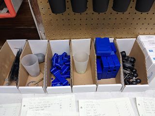
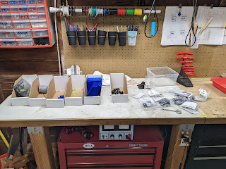
During that time, I also got overwhelmed with my garage and did some cleaning, and also rigged up some self-adhesive LED strip lighting on a cheapy piece of metal angle from Home Depot to act as "under counter lighting".


Anyway, back to the work at hand. The core code is in st7789vi_frame_writer.cpp and st7789vi_frame_writer_smi.cpp. As you can see, once you get the driver set up, you basically just write to a device file, and out go the bytes. The BCM2835 SMI peripheral takes care of generating the square wave with the timings you asked for, and strobing a !WRITE line appropriately.

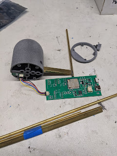
With that in hand, it was time to create a PCB.


Behold the PCB. All hail the PCB. Except ... well. Of course there was a hitch. The LCD panel requires a backlight voltage of 3.2V. Wait ... what??? Most LCD panels require something like 20V. Except this one. And so the boost LCD driver chip I was using, with a 5V input, cannot go so low, and I cannot PWM-dim the display. Dimming is kinda important when your display is 1,000 nits and people might want to use it at dusk or even night-time. I'm fixing this in the next spin. Stay tuned.

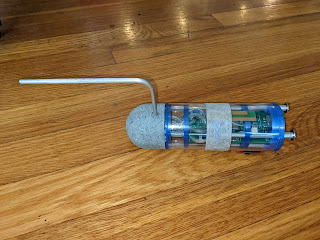
I then built a housing for this thing, to hold the parts together in the most obvious way possible:


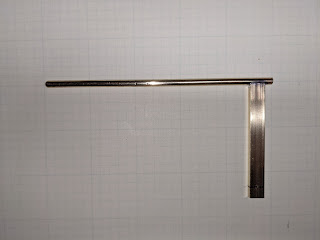
I mounted it in N291DR using the forward frame struts, using some RAM mount components and a 3/4" padded tube clamp from the hardware store:


And here it is in flight today (see this link for a video):


Of course, no good deed goes unpunished. The WiFi setup on the display started flaking out for reasons completely unknown to me. I could not repro these on the bench today. I will try a different set of hardware and see where we go. It's just a WiFi base station on a RasPi with hostapd; how hard could it possibly be? #famouslastwords

Sunday, June 12, 2022

Project update: Shipping

We have been shipping units to friends, and hope to report results soon. Meanwhile, enjoy these photos of the Airball units as shipped; a sort of simulated unboxing!


Project update: The mount

Mounting the probe is always the big challenge. The latest round of builds produced this thing, which combines a "vee block" and "tee square". Note the metal hardware to align the probe. A huge amount of work and prototyping went into designing and building this, and it's not even quite done yet.


The design uses AN hardware in important locations, and on the airplane, it looks like this:


I am also now printing the important parts of the mount in 100% infill PETG, and the whole design has been beefed up considerably. This replaces a whole host of RAM mount predecessors -- once my bush pilot friends got a hold of the RAM mount, they laughed at how wiggly it was! The new design is rock solid; if it fails, then your plane has other problems besides Airball. :)


Project update: The display

The display is kind of the root of all evil in this system. We require a pretty beefy processor (not a monster -- just not a tiny microcontroller) to display the necessary (approx.) 20 FPS anti-aliased graphics. We need a bright screen, but given the givens, we don't have one because we have yet to successfully build a new custom system with a sunlight readable LCD module.

Our latest system is this, which uses a Raspberry Pi 3B+ and a Waveshare 3.5 inch LCD:


Project update: The probe

For good or for ill, the heart of our system is our airdata source, i.e., the probe. This is roughly what our latest-model probe looks like:


Notice that the probe parts are made of HP MJF Nylon, and the probe is equipped with an explicit static probe made of silver-soldered brass.

This probe has been shown to provide very consistent airspeeds in a wind tunnel, under varying orientations. Basically, any air data quality problems are now gone. Check out this video:


Another project update

It's been a while since I posted on this blog. I assure you that work on Airball is going strong, but things have shifted a bit.

I am basically at the point where the "technology demonstrator" phase is done, and I need to find a beachhead market and get this thing into people's hands. This may involve a "hobbyist" release made of 3D printed materials that people can make (per the original plan), or it may involve handing this off to a corporation, or ... any of a number of other options.

In order to get this pitch honed, I have been working on putting working prototypes in people's hands. I have at least one STOL / bush flying friend right now who is using this thing regularly, and we are figuring out what the best user interface abstractions can be for his type of flying.

Below is the situation in April 2022, with 4 systems (plus one "off camera") ready to send out. We have since found tweaks and improvement, which I will detail in subsequent blog posts, focusing on the probe; the display; and the mounting.


Saturday, January 29, 2022

Project update

Greetings folks. It's been a while since I posted an update. I've been working heads-down super hard, so this is actually good news. Some random items...

First of all, IAS accuracy is brilliant when I went to a non-porous materials for the entire air path. I verified this by blowing into the probe and comparing a water manometer with the readings. The porous 3D printed material creates enough leakage to create enough of a flow to create enough of a head loss to change the results dramatically. The new probe nose is made out of HP "multi-jet fusion" plastic by http://jawstec.com/ and the prototype probe looks like this:


Note the tape because the temperature sensor bits were still in the mail. This is all getting improved.

I have moved to a brass brazed static probe that has a rectangular section to hold it in place securely, rather than the bent tubes that wiggled out of position. This is what it looks like, in progress and completed:


I have moved the probe protocol from TCP to UDP, to improve instant-on reliability. I have also made the Raspberry Pi display the Wi-Fi base station, to off-load complex work from the ESP32 probe. I completed the work on the Web configuration editor.

I updated the climb rate algorithm in the altimeter -- now it attempts to fit a polynomial to the latest N pressure altitude readings, and then reports the slope of that polynomial at the current time. It seems to be a better balance between stability and instant feedback. We'll see how it fares.

I added audio to Airball! I added a micro-framework for audio output, then added two sound "schemes". One is "FlyONSPEED" -- using the work of my friends at http://flyonspeed.org/. The other is "stallfence", which is just basically a simple progressive yaw and stall beeper. I hope to get more user feedback on what people want to see from audio!

I'm in a full-on production run of 5 units, followed by 10 more units. Wish me luck!