Sunday, March 12, 2023

Shenanigans with Jimmy

I think this is the first time I mention my friend Jimmy O'Neal on this blog. Jimmy is an Airball early adopter and development partner, has been an absolute joy to work with. He is a stupendous backcountry pilot, outdoors and motorsports enthusiast, and overall great dude, and over the past 6-9 months has really helped get Airball to the next level. He was the one who asked for a mini-display on the glareshield, and in so doing put us on the path to a really awesome product vision.

Last month, I did my longest XC yet, flying from San Jose to Camarillo to hang out with Jimmy, go flying, and try things out on his RANS S-20. Here's are a few interesting workshop photos:
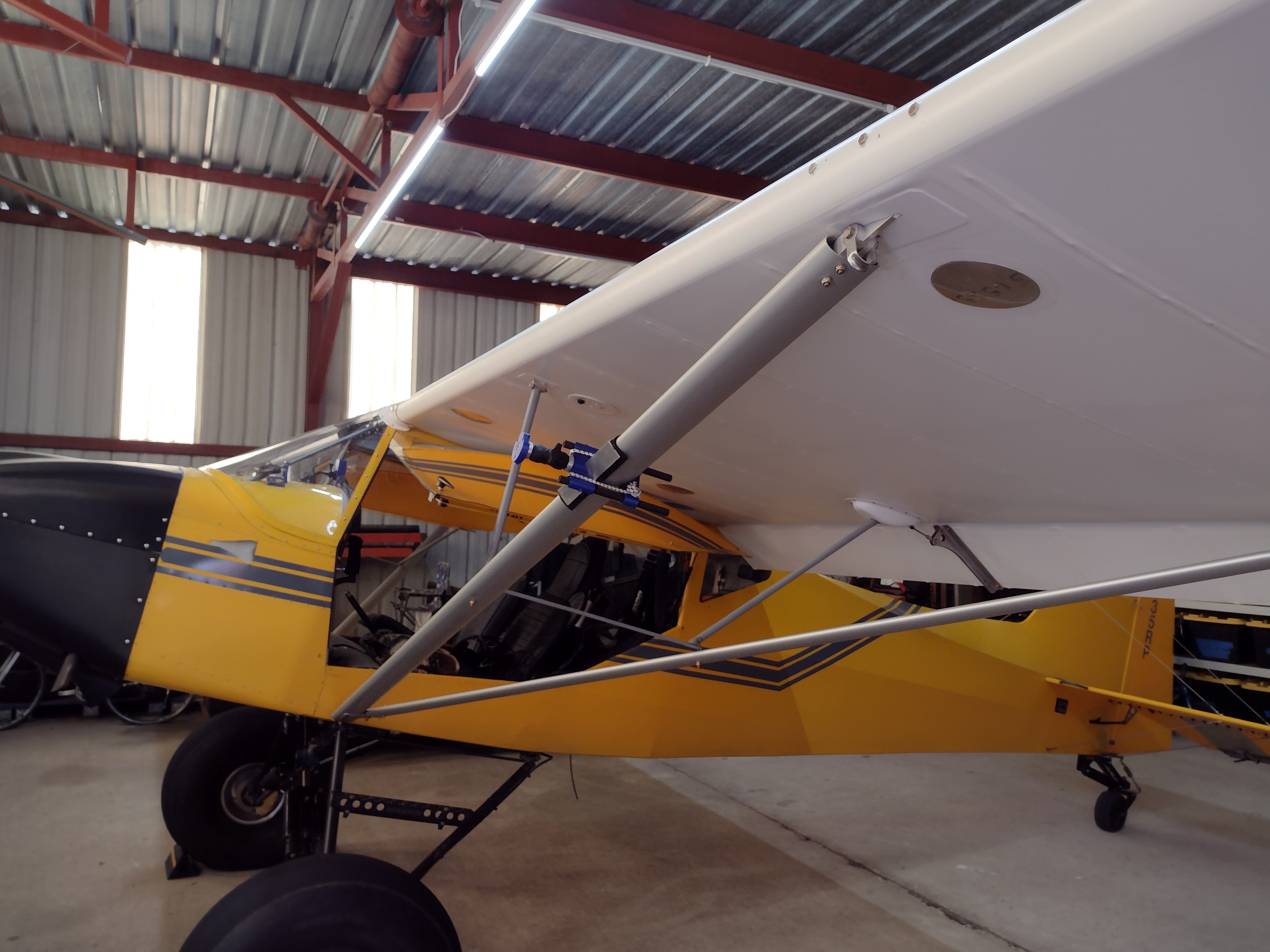


In particular, note that we mounted the Airball probe on a wingtip pole. We were hoping to get even farther out of the propwash, and also into a more convenient location for a "wired-in" installation since most wingtips have some wiring going to them already.

We found out that the airflow about a foot to a foot and a half ahead of his wingtip is moving spanwise outboard a bit, such that the relative wind points outboard by about 5 or 6 degrees. We scratched our heads and could not figure it out....

One go-to explanation is that this is the upstream effect of the wingtip vortices. Which makes sense, right? In a subsonic flow, we expect upstream effects, so why not? Except that we would then expect the magnitude of this effect to change with the amount of circulation produced by the wing, i.e., the angle of attack. And yet Jimmy observes no such effect (or if it's there, it's too small to notice). I am totally weirded out, and the usual "call a scientist" response has yet to yield a comprehensive explanation.

There was a lot of lovely scenery on my XC! I'm hoping to visit again soon and do more aviation experimenting!


The display, and the saga of the recalcitrant USB

I have been refactoring the display code quite extensively, as I mentioned before. Well so now I have support for an "adjustment knob" that acts as a USB HID device, and I'm using the Adafruit Rotary Trinkey for its compactness (even though any USB "volume and play/pause" product would work too).

The current thrown-together prototype of this setup looks like this:

The idea is that the little controller sits inline on the USB cord powering the RPi and also acts as its USB peripheral. This means that the USB-A socket on the RPi acts as both a Downward Facing Port (to connect to its USB HID peripheral) and an Upward Facing Port (to receive power). This is not "legal" except with USB-C and USB-PD, but luckily, the RPi just connects its +5V rail directly to the USB VBUS and so it doesn't know the difference.

Luckily, I say....

Now the problem was, when the whole thing is powered up all at once, the RPi would not connect properly to the USB peripheral. It would see it, and produce the correct device files in /dev/input/, but no Linux input events would show up. The only way to get things to work was to:

  • Turn on the RPi;then
  • Connect the USB HID peripheral.

As you might imagine, this is not the nicest UX. I tried and tried. I posted on forums. I debugged like the wind. Oh my gosh this soaked up so much freaking time. And eventually I realized, this is just not going to get solved. There are rumblings that this may be a problem with the SAMD series of processors and their hardware USB implementation, but this is not going to help anyone.

My first cut was to use a 555 timer to make a delayed power-on circuit. This was valuable simply because it taught me how to make 555 circuits; I had never done that before (imagine that!). Also, when setting the RC values for the delay, I ended up choosing "impossibly" high resistor values, meaning that I could not even measure the behavior of my circuit because my multimeter would interfere with it! Lesson learned; welcome to the real world. I ended up with something that would actually turn on the USB peripheral after about 10 seconds, using a reed relay:

This is great except -- it did not work. Why I have no idea. but it was time to cut my losses, and so I just added a switch to my "controller" module. The user can just turn it on after the display, and we can hope for the best.

The result, anyway, is that now we have something where all the settings are available using a multi-function knob. Check out this video on the bench:

https://photos.app.goo.gl/ArszEDoMNh4jueAG9

and this one on a bumpy flight where my poor wife Melissa got airsick, but was a total trooper and continued to work as the test flight engineer while I kept the greasy side of the plane pointed downward:

https://photos.app.goo.gl/oWr9kvYxjYEYKVmQ8

This is probably as far as I'm going to go with the RPi 3A+ for my displays. I'm told that RPi CM4's are going to be available again soon. Compared to the heartache and pain of dealing with all this nonsense, I'm sure I could build a CM4 carrier board without too much trouble. Stay tuned for that. If / when I do, it will be super compact and wonderful!